Digital Voltmeter
What is a Digital Voltmeter
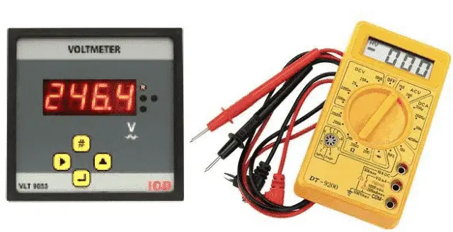
Digital Voltmeter abbreviated as DVM is an instrument used to measure the electrical potential difference between two points in a circuit. The voltage could be an alternating current (AC) or direct current (DC). It measures the input voltage after converting the analog voltage to digital voltage and displays it in number format using a convertor. The usage of digital voltmeter has increased the speed and accuracy with which the readings are noted. A typical DVM is shown below.
Fig. 1 – Digital Voltmeter and Multimeter
How does a Digital Voltmeter Work
The working principle of a Digital Voltmeter can be categorized into five functional sections. They are:
- Pulse Generator
- Voltage Control and Gating
- Counting Clock Pulses
- Analog to Digital Conversion
- Latching and Display Section
Pulse Generator
In electronics, It is called a ‘Clock’ which generates pulses generally achieved using 555 timer chip.
Voltage Control and Gating
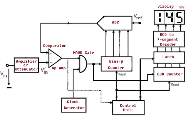
This section of control and gating is based on an integrated circuit called the Comparator. This IC compares the two voltages and signals for which of the two voltages is larger. One of the voltage is the input voltage ( Vin) and the other will be the voltage across the capacitor.
Voltage is monitored across the capacitor and signals are generated when the voltage becomes equal to the voltage to be measured (Vin) and the charging starts at zero volts. The comparator does not draw any appreciable current, otherwise it will interfere with the constant-current charging. To achieve near-zero input current, an Op-Amp is used as a comparator.
The Op-Amp (Operational Amplifier) is a chip with two inputs labelled + and – called the non-inverting and inverting inputs. The voltages at these points are called V+ and V- respectively. It has only one output. Like any other chip, it requires power and ground connections. If the voltage at the + input of Op-amp is greater (more positive) than the voltage at the – input (V+ > V-), then the output is high i.e. near to Vcc else the output will go low, near Vee .
Counting Clock Pulses
The number of clock pulses that occur between the start and stop charging signals is counted. It is also defined as the measure of the elapsed time. While the capacitor is charging, the pulses generated are counted with the help of an IC, which is a “Divide by Ten Counting Chip”. The logic pulses generated by the timer IC is fed as an input and the pulses from 0 (0000 binary) to 9 (1001 binary) is counted repeatedly putting out the binary bits corresponding to the number of pulses counted. Once the counting gets past the value “9”, the binary bit output rolls over to 0000 again, and the same process continues.
The voltmeter will work by counting the pulses from the time the capacitor starts charging, and the time the comparator detects that the capacitor voltage overrides Vin and therefore changes its output state. To achieve this a simple NAND gate is used in the circuit. Output pulse train is connected to one input of the NAND, and the second input is connected to the control unit.
A current capacitor charging circuit that can be turned on and off and reset to zero volts by the start and stop charging signals automatically is an important aspect in a Digital Voltmeter. The capacitor has to go through a cycle of charging and discharging.
ADC (Analog to Digital Converter)
An A/D converter or ADC (Analog to Digital Converter) converts an analog voltage sample and returns a binary number that describes the sample.
Latching and Display Section
The number of pulses counted is displayed in a numerical format using a seven segment LED display. The latch is used to statically display the final result of one capacitor charging cycle operation, even while the next cycle is in progress.The latch has four inputs and four outputs. It passes the logic states on its inputs through to its outputs.
Fig. 2 – Basic Block Diagram of Digital Voltmeter
Types of Digital Voltmeter
Digital Voltmeter is broadly classified into four types. They are:
- Ramp Type Digital Voltmeter
- Integrating Digital Voltmeter
- Continuous Balance Digital Voltmeter
- Successive approximation Digital Voltmeter
Applications of Digital Voltmeter
- Digital Voltmeter is used to know the actual voltage of different components.
- DVM is widely used to check if there is power in the circuit, such as mains outlet.
- Knowing the voltage across a circuit, current can be calculated.
Advantages of Digital Voltmeter
- Digital display of the output eliminates human reading errors.
- Readings are accurate and fast compared to analog meters.
- Digital Voltmeter is more stable and reliable.
- Smaller in size and cost-effective.
- DVM can measure both AC and DC voltages.
- Latest DVM are built with micro controllers which stores the readings for further processing.
- DVM is void of Parallax errors.
- DVMs have automatic range selection.
- DVMs have high input impedance.
Disadvantages of Digital Voltmeter
- Digital Voltmeters are prone to damage if the voltage is increased beyond the limit.
- The display depends on the external power source or battery.
- While measuring the voltage, there are chances of the digital voltmeter getting heated up.This might output wrong readings.
- When a fluctuation occurs in a circuit, the digital voltmeter cannot read and displays an error.
- Speed of operation is limited due to the digitizing circuit in digital voltmeters.
- It is very hard to spot the transient voltage spikes.
- The A/D converter has a limitation on word length which causes quantization noise giving rise to errors in measured values.


No comments